 Pi-CO2: Patented Core Technology
The technology uses well known processes and standard components in a novel configuration. Our development team includes world class industry leaders in carbon capture, oil and gas, thermodynamics, and complex fluid flow. The modeling, manufacturing specifications and financial estimates have been well vetted with leading global manufacturers and design teams.
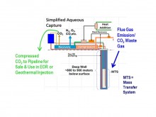
In a brief overview (see figure beside), the Pi-CO2 capture method uses water as a physical solvent, circulating the water and emission gas through a cascade mass transfer system (MTS) located in a sealed deep large diameter well (or suspended in deep water) under up to 60 bar hydrostatic pressure. The hydrostatic pressure significantly increases the solubility of gases in water. The system is closed loop with the high pressure non-dissolved separated gas fraction diverted to the surface and combined with heat to recover compression energy.
The flue gas is injected in the MTS at depth in the deep water column. The gases (CO2 and lesser competing gases) are concentrated through a cascading series of absorbers in the MTS (proprietary detail not shown). Water returning to the surface from the MTS becomes less pressured allowing for gas ex-solution; this ex-solution drives the water circulation (gas lift pumping). The non-CO2 ex-solved gases are sequentially removed in the return line to produce nearly pure CO2 product.
The system integrates compression and energy recovery processes at the surface to reduce parasitic load with heat exchange and turbo-machinery (similar to a Compressed Energy Storage System). Thermodynamic modeling confirms the energy demand and recovery potential, step-wise mass transfer of the CO2 into the water, and the ex-solution purification steps. More details on key points of this technology can be found in the paper (available here) presented at the 12th GHGT Conference in October 2014 at Austin (TX), USA.
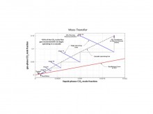
 Chemical and thermodynamic modeling show excellent prediction for CO2 and trace gas solubility, gas recovery, and energy recovery. Recent multi-phase fluid flow modeling has shown that we can achieve equilibrium and 90% recovery with our current mass transfer stage and system design (see figure beside).
Collectively, this projects highly successful outcomes in bench, pilot, and demonstration stages.
Comparison to Competing Technologies
State-of-the-art in competing capture technologies includes amine and ammonia chemical capture systems with recent introduction of membrane, cryogenic, and carbonate systems. Key limitations include 1) high parasitic energy demands, 2) high costs, 3) hazardous constituent creation and/or poisoning and plugging for membranes, 4) large land footprint, and 5) high thermal demand (carbonates). Pi Innovation’s process addresses each of these limitations. Key comparison elements are provided in the following table:
|
Differentiators and Competitive Comparison |
|||
|
Comparison Criteria |
Pi-CO2 Aqueous Capture |
Competing Technologies |
Benefit |
|
Lower Delivered Cost |
$35-45/mt CO2 |
$70-85/mt CO2 |
>45-50% |
|
Lower Parasitic Energy |
<9 to 23%* |
> 30% |
>20-70% |
|
Meets Industry Cost Goals$ |
YES |
NO Exceeds |
Feasible Margins |
|
Carbon Neutral Solvent |
YES |
NO |
Carbon Credit |
|
No Hazardous Chemicals |
YES |
NO |
Low Risk |
|
Potential Mercury Removal |
YES |
NO |
High Value |
|
High Net Profit, High IRR |
YES Low Price |
NO High Price |
High ROI |
|
Notes: *Range of parasitic energy recovery varies with the emission source CO2 concentration. $Cost Goal based on delivered price oil industry currently pays for geologic or natural sources of CO2 (currently approximately $40/mt). |
|||
Use of Pi-CO2 technology as part of the CO2-DISSOLVED system
As described above, the Pi-CO2 technology was initially designed for applications to EOR and EGS (where CO2 can be used as a working fluid). The application of this technology to the CO2-DISSOLVED concept only requires the CO2 dissolution step, with no need for further degasing at the surface. As a consequence, we plan to mainly rely on the MTS to both capture the CO2 from the gas flue by dissolving it in the circulating brine, and then inject the CO2-laden brine back to the aquifer instead of being lifted up to the surface. The main issue that could be thought of beforehand is on the possible difficulties related to the full integration of the MTS as part of the injection well: it could be a potential limiting factor in terms of achievable brine circulation flow rate, and complexify the maintenance operations in the well. Partnering in Innovation, CFG Services, and BRGM are currently working on the best design options for the integration of the Pi-CO2 technology inside the doublet. The option of using a third large-diameter well dedicated to the CO2 capture operations is also considered.
Dernière mise à jour le 30.05.2018


